 |
The requirement for safety testing medical electronic (ME) equipment is regarded as essential to ensure that apparatus does not pose any danger to users or patients. To meet this need, many different standards have been published to describe what is considered safe for the patients and operators of ME equipment.
The most widely used standard is IEC 60601. Although this is a type standard associated with the design and development of ME equipment, most biomedical engineering departments continue to use it as the basis for the regular testing of medical devices, and/or after service or repair.
Clearly, safety testing at the design stage and at the end of the production line are vitally important, but what about when the equipment enters service? This was the basis for the introduction of IEC 62353, the newly published international standard for medical electrical equipment—recurrent test and test after repair of ME equipment.
Testing Times
Each part of the medical device market has different electrical safety testing requirements. The motivation for most test requirements is the need to comply with statutory legislation and meet public liability considerations. But even when the need for safety testing is recognized, other factors come into play. One example is the culture of organizations, which can affect the type of test equipment used and the frequency of testing. Another factor can be the environment in which testing is undertaken, which can vary from the production line, the laboratory, an operating theater, to the patient ward.
The introduction of IEC62353 is intended to streamline this position and harmonize all standards that aim to control the safety of electromedical (EM) devices used in the treatment, care, and diagnosis of patients.
Enter IEC 62353
IEC 62353 Medical Electrical Equipment—recurrent test and test after repair of medical electrical equipment—defines the requirements of ensuring the in-service electrical safety of EM equipment and systems. As far as possible, it is an attempt at standardizing the safe operation and testing of ME equipment, while respecting specific local requirements and meeting increasing demands for risk management.
In meeting these aims, IEC 62353 incorporates tests beyond those of type testing. Specifically, it seeks to provide a uniform and unambiguous means of assessing the safety of medical equipment, while maintaining the relation to IEC 60601-1, and minimizing the risks to the person conducting the assessment.
Importantly, the new standard recognizes that the laboratory conditions described in IEC 60601-1 cannot always be guaranteed when in-service testing of medical devices is undertaken.
In-Service Test Requirements
As a type-testing standard, the current IEC 60601 does not provide any guidance to standardizing test requirements once an item of ME equipment has passed the design phase.
Once a medical device enters into service, a number of potential test scenarios arise, including:
- Acceptance testing, also referred to as initial or reference testing. This test is carried out before a new medical device is authorized for use, and is undertaken to ensure correct and complete delivery. Acceptance testing is often not limited to electrical safety tests, with some basic function tests being applied to verify correct performance.
- Routine testing, also referred to as PPM, preventive product maintenance. This form of testing is often conducted at fixed intervals, which vary among types of equipment, manufacturers’ recommendations, and risk-assessment procedures undertaken by individual biomed or medical physics departments. Routine testing is not limited to safety testing and often includes the verification of correct functionality.
- After service and repair testing—carried out following a repair, adaptation, or product upgrade. It is often part of a service carried out by in-hospital mechanical or clinical engineering teams. In many cases, more rigorous electrical safety testing is needed after the replacement of components or reconfiguration of medical devices.
Visual inspection
In most cases, up to 70% of all potential faults in an item of ME equipment can be detected during visual inspection. Although visual inspection is not clearly defined in IEC 60601, its inclusion is a fundamental requirement of all routine test and maintenance procedures.
Visual inspection is a relatively easy procedure to ensure that the medical equipment in use still conforms to the manufacturers’ specifications and has not suffered from any external damage and/or contamination.
The following are typical visual checks that should be made:
- Housing enclosure—look for damage, cracks, etc;
- Contamination—look for obstruction of moving parts, connector pins, etc;
- Cabling (supply, applied parts, etc)—look for cuts, wrong connections, etc;
- Fuse rating—check correct values after replacement;
- Markings and labeling—check the integrity of safety markings; and
- Integrity of mechanical parts—check for any obstructions.
However, to identify all potentially dangerous faults, visual inspection should be linked with a program of periodic inspection and testing that is capable of revealing any “invisible” electrical faults such as insulation integrity, effective ground bond connections, unacceptable leakage, and other potential problems.
IEC 62353 Insulation Resistance Test
Unlike the IEC 60601-1 tests, the new IEC 62353 includes a method of testing the insulation of an EM device. Three different insulation test methods are recommended for different types of ME equipment. The test methods are:
- Insulation between mains parts and ground—this test is used to verify that the mains parts are adequately insulated from ground (Class I) or the enclosure (Class II).
- Insulation between applied parts and ground—this test is used to verify that the applied parts are adequately insulated from ground (Class I) or the enclosure (Class II). It is designed for Class I and Class II, BF, and CF equipment only.
- Insulation between applied part and mains—this test is used to verify that the applied parts are adequately insulated from the mains parts and is applicable to Class I and Class II BF and CF equipment only.
IEC 62353 Ground Bond Test
The ground bond test proves the integrity of the low-resistance connection between the ground conductor and any metal conductive parts, which may become live in fault situations with Class I medical devices.
Although many Class I medical devices are supplied with an equipotential point, most, if not all, medical devices require multiple ground bond tests to validate the connections of additional metal accessible parts on the enclosure.
IEC 62353 requires a minimum test current of 200mA, either AC or DC, but when using a DC test current, the resistance must be tested in both polarities of the test current. The open circuit voltage of the current source should not exceed 24V.
The highest test reading will determine the pass or fail result of this test in comparison with different test limits included in IEC62353 for different types of equipment. For example, the test limit for a Class I device including a power cable not exceeding 3 meters is 300mV.
Higher test currents of 25A or 10A have been traditionally favored, based largely on IEC 60601-1 requirements. The assumption was made that higher currents could best detect any damaged conductors present. In addition, when analog instruments were widely used for low-resistance measurement, it was often necessary to use high-test currents to produce sufficient voltage drop across the sample to generate the necessary needle deflection.
However, higher test currents—of 10A or more—might potentially be destructive to parts of the device under test, which are connected to the protective ground but have a functional purpose, such as screening. As such, consideration should be given to the test current.
With modern electronics and digital technology, the use of higher test currents is regarded as no longer necessary—a fact recognized by IEC62353 with its 200mA minimum current.
On the other hand, low-test currents—of less than 8A—may not always overcome problems associated with contact resistance caused by constriction, pressure, or film resistance factors, and may therefore show a relatively higher reading than there is and indicate unnecessary failures.
Recently, new test technology has been pioneered in the form of a new low-energy, high-current test that overcomes the previous contact-resistance problems that inhibited the wider application of protective ground testing using 1A or 200mA test currents.
Importantly, the new low-current test technology enables valid ground continuity tests to be carried out using battery-powered testers, significantly increasing the portability and versatility of handheld safety analyzers used in in-service safety testing routines, significantly speeding up the testing process.
IEC 62353 Leakage Testing
Research has shown that it is current rather than voltage that is the source of electricity-related injuries and deaths. As a result, there are stringent rules on the design of medical equipment to ensure that the patient and operator are not exposed to those currents that do not form part of the functional operation of the device. These are called leakage currents.
In the interests of helping to guarantee safer practice and the repeatability of test measurements, IEC 62353 defines different types of leakage current tests—one for total equipment leakage and another for applied parts leakage currents.
IEC 62353 specifies three methods— direct, differential, and alternative—that can be used to determine the leakage of EM equipment.
Direct Leakage Method
The direct leakage method included in IEC62353 is the same as that in IEC 60601, measuring the true leakage through a body model measuring device to ground.
The main benefits of this method include the ability to measure both AC and DC components, allowing direct comparison with the manufacturer’s IEC 60601-1 tests, and measuring lower leakage values typically of less than 100µA.
However, one of the main disadvantages of this method is that the 1KV body model resistor is connected in series with the protective ground conductor that will form an “equal” parallel connection with the human body, thus presenting a potential hazard to the operator.
Another disadvantage is that secondary ground connections will produce a lower reading, thus potentially allowing faulty equipment to pass the test. The direct method does therefore require a fully isolated device under test and must be performed on a terre neutral supply and in each polarity of the incoming mains supply to guarantee measurements are taken at the maximum potential leakage current.
Keeping It Safe
Follow this checklist for safety testing and keep all the bases covered.
- Ensure that the operator of safety test equipment is properly trained on both the safety analyzer and the device under test to prevent unneccessary danger during the safety test.
- Always ensure that the device under test does not pose any danger to the user and/or people within the vicinity of the safety test. Stay aware of moving parts, open conductors, live components, heat, etc.
- Ensure that leakage measurements are performed while the equipment is in full operation mode, including its subsystems and components.
- Ensure high accuracy and repeatability of leakage measurement readings. Some manufacturers might specify full-scale accuracy, which will affect the accuracy of low-leakage measurements.
- Ensure that contact resistance is taken into account when measuring the ground continuity at low currents (<8A). Contact resistance can influence the readings and cause unnecessary failures of the device under test.
- When determining the correct means of testing a specific medical device, ensure that the chosen safety test procedures are applicable to the device under test and are clearly documented for future use.
—JB
Differential Leakage Method
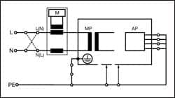
The differential test method measures the leakage current as a result of imbalance in current between the live and neutral conductors.
The main advantage of using the differential leakage method is that the ground conductor remains intact during the measurement, thus providing safer working conditions. Differential measurement of leakage also does not require an isolated device under test because it relies on comparing the difference in current between the live and neutral conductors to measure the complete leakage of the device being tested, including leakage caused by secondary connections.
The main disadvantage of using the differential method is reduced accuracy on lower leakage values, because typical leakage values of more than 100µA are required to obtain stable and reproducible readings. Measurements can also be influenced by the presence of magnetic fields—the principle of measuring differential current—and measurements must be done in both directions to identify the worst-case scenario. The differential leakage measurement method is also only able to measure the AC component.
Alternative Leakage Method
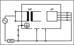
The alternative method is similar to a dielectric strength test at mains potential, using a current limited voltage source at mains frequency. The live and neutral conductors are shorted together and the current limited voltage is applied between the mains parts and other parts of the equipment.
The main advantage of using the alternative method included in IEC 62353 is that the device under test is not connected to the mains supply and provides the safest possible test conditions for the operator. In addition, this measurement is only taken in a single polarity and is similar to a dielectric test at mains potential using a current limited mains frequency supply.
Leakage measurements achieved using the alternative method are highly repeatable and provide a good indication of deterioration in the dielectrics of the medical device under test.
The disadvantages of using the alternative method are that measurements cannot be compared with previous IEC 60601-1 tests, and those active parts of the circuitry that require mains potential between live and neutral cannot be tested for possible leakage. For this reason, the alternative leakage method is only relevant for certain types of EM devices.
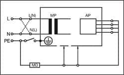
IEC 62353 defines two different kinds of leakage current tests for applied parts—equipment leakage current that tests for total leakage deriving from the applied parts, enclosure, and mains parts combined to real ground; and applied part leakage current that checks for total leakage deriving from the combined patient connections within an applied part to ground and any conductive or nonconductive parts on the enclosure.
 |
| Figure 1: Equipment Leakage Direct — Class I |
Equipment Leakage
The equipment leakage test is applicable to both Class I and II, B, BF, and CF equipment, and measures the total leakage (RMS) deriving from the applied parts, enclosure, and mains parts combined to real ground.
All applied parts (B, BF and CF) and grounded (enclosure Class I), and nongrounded accessible conductive parts or nonconductive accessible parts (enclosure Class II) are grouped together and connected to ground via the 1kø measuring device (body model).
Measurements are done in both polarities of the incoming mains, excluding alternative method.
 |
| Figure 2: Equipment Leakage Differential — Class I |
The IEC 62353 equipment leakage can be performed using a direct, differential, or alternative method.
Figures 1, 2, and 3 provide a schematic representation of the equipment leakage test on Class I (grounded) ME equipment.
Applied Part Leakage
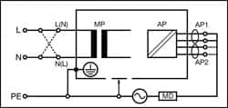
The applied part leakage test measures the RMS deriving from the combined patient connections within an applied part to ground and any conductive or nonconductive parts on the enclosure.
 |
| Figure 3: Equipment Leakage Alternative — Class I |
This test is applicable to floating-type (BF and CF) applied parts only—either Class I or II. All patient connections of a single function within an applied part shall be connected together (BF and CF) and measured one at a time.
The test is conducted by applying a current limited (3.5mA) mains potential sinusoidal 50Hz or 60Hz signal between the applied part and the enclosure and ground connection of the EUT connected to real ground.
Measurements are done in both polarities of the incoming mains—direct method only.
The IEC 62353 applied part leakage test can be performed using a direct or alternative method.
 |
| Figure 4: Applied Part Leakage Direct — Class I |
Figures 4 and 5 provide a schematic representation of the applied part leakage test on Class I (grounded) ME equipment.
Conclusion
The electrical safety testing of ME equipment is a crucial part of the overall safety validation of medical devices and requires specialized test equipment.
The introduction of the new IEC 62353 standard will provide:
- A global test reference to allow uniform testing;
- Development tools for safer and suitable test sequences; and
- A method of record keeping and maintenance procedures.
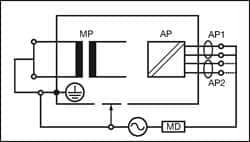 |
| Figure 5: Applied Part Leakage Alternative — Class I |
Although the onus will remain on the manufacturers of medical devices to advise on appropriate tests for their equipment, the new standard will clearly have a significant impact on medical service companies and clinical engineering, EBME, medical physics, and other technical departments.
In all cases, when choosing a suitable electrical safety analyzer, care should be taken to ensure that it can be used to test in accordance with IEC 62353 requirements and that it is capable of performing accurate and repeatable test routines.
John Backes is product manager, Rigel Medical, Peterlee, UK, www.rigelmedical.com. For more information, contact .


