The Digital Imaging and Communications in Medicine (DICOM) standard has been actively used worldwide for more than 25 years. The DICOM standard specifies a nonproprietary data interchange protocol, digital image format, and file structure for biomedical images and image-related information. It’s also the standard that defines how medical instrumentation communicates on a network to transfer clinical information—notably, digital diagnostic images.
DICOM is always difficult to write about. There is so much information that is part of DICOM communication that it can be tough to zero in on any one aspect while keeping the big picture in mind. In this, part 1 of a 2-part series, Networking reviews some of the main characteristics and concepts of the DICOM approach. Part 2 continues the discussion with DICOM network associations. Later in part 2, we’ll review OEM DICOM conformance statements and how they can be useful to the HTM professional.
A Little Background
DICOM is a huge, varied, and detailed standard, as it endeavors to cover all the specifics that make up network communication and image maintenance. The DICOM standard allows for a lot of variability and flexibility to facilitate dependable data transfer among varying manufacturers. This approach ensures interconnectivity by confirming the connection between application entities (AEs, what DICOM calls the devices on the network). It also ensures interoperability by confirming that the AEs understand the context of the content being exchanged. Since the DICOM standard is so large, OEMs use the DICOM conformance statement to identify which portions of the standard they use to achieve DICOM compatibility.
DICOM addresses five general application areas: network image management, network image interpretation management, network print management, imaging procedure management, and off-line storage media management. All of this occurs by communicating on a network. DICOM can also be considered as the protocol and language of a PACS (picture archiving and communication system) network.
Data Structures
DICOM breaks down the image and associated image information into the smallest possible elements, covering everything in its 18-part standard. (See the sidebar for a complete list of the sections, which can also be viewed and downloaded at dicom.nema.org.) For example, when addressing a CT image, DICOM identifies all the details associated with that image—from gantry angles, to gray scales used, to radiation dosage. However, not every OEM will use every possible detail: obviously an OEM is not going to use MRI information elements for a CT machine, for example. However, the pieces of information a CT OEM uses for a CT image would be defined in the conformance statement.
[reference float=”right”]DICOM Sections
PS 3.1: Introduction and Overview
PS 3.2: Conformance
PS 3.3: Information Object Definitions
PS 3.4: Service Class Specifications
PS 3.5: Data Structure and Encoding
PS 3.6: Data Dictionary
PS 3.7: Message Exchange
PS 3.8: Network Communication Support for Message Exchange
PS 3.9: Retired
PS 3.10: Media Storage and File Format for Data Interchange
PS 3.11: Media Storage Application Profiles
PS 3.12: Media Formats and Physical Media for Data Interchange
PS 3.13: Retired
PS 3.14: Grayscale Standard Display Function
PS 3.15: Security Profiles
PS 3.16: Content Mapping Resource
PS 3.17: Explanatory Information
PS 3.18: Web Access to DICOM Persistent Objects (WADO)
PS 3.19: Application Hosting
PS 3.20: Transformation of DICOM to and from HL7 Standards[/reference]
DICOM builds a map of the information by identifying all the small pieces of data that together define instances of real-life events or objects, called data elements. For example, there is an element for the patient’s date of birth. The element defines how to format its own attribute or value, eg, YYYYMMDD.
The Data Dictionary portion of the DICOM standard (PS3.6) lists the codes used for all DICOM data elements. In it, the elements and their attributes or values are grouped with like elements and categorized according to a value representation classification system with 27 categories. For example, the Person Name category contains other groups and elements associated with identifying information, such as the person’s date of birth, age, address, insurance company and numbers, sex, race, and attending physician.
Using value representations, these describing elements are grouped together to build an information module—the next information building block. The intent is to pull together related data elements in a reliable, structured manner. For example, the patient identification module will group all patient identifying elements from all the associated value representations. From there, DICOM information entities (IEs) are built from the related information modules. As an example, the Common Patient IE includes the patient, specimen information, and clinical trial modules.
At the top of the information hierarchy is the information object definition, or IOD. IODs are built from gathering applicable IEs. An IOD for a CT image would contain the patient, study, series, frame of reference, equipment, and image IEs. All DICOM data processing is done in terms of these top-level IODs.
DIMSE
Thus far, our discussion has been about DICOM’s data format. To complete the picture, we will also review the command set, or the list of functions that need to be applied in order to actually make use of the data. Service class is DICOM’s term for these commands, indicating what you’re going to do with the IOD. When the IOD is combined with the service class, it becomes a service object pair, or SOP. (SOPs are defined and identified in PS3.4.) In DICOM-ese, the service class commands are also called the DICOM message service element, or DIMSE.
To operate on the data, the service class defines the function, such as print, store, view, and transfer. To complete the command, DICOM defines a sort of client/server relationship. Consider a DICOM statement such as “I am sending a CT image to you.” In this sentence, the “CT image” is the data, or IOD, and “sending” is the action or command being dictated by the service class or DIMSE. Together, they make up the SOP “sending a CT image.” The “you” in this statement is the client or user, also known as the service class user (SCU). The “I” is the server or provider of the service, which is called, naturally enough, the service class provider (SCP).
Note that DICOM makes a distinction between normative and composite data and commands. Calling data normative or normalized indicates that the IOD or DIMSE is referring to a single real-world entity. The Patient IOD, for example, represents just the patient parameters. In contrast, composite data are mixtures of several real-world entities. A CT image IOD is a composite, as it can contain some patient information, a patient study, and attributes (data elements) related to the scanner itself. Therefore, when you see a DIMSE command such as C-STORE with a C prefix (rather than a D prefix), you’ll know that it’s operating on composite IODs.
So that’s the setup. DICOM defines the data content in great detail by using a hierarchy to build up to the IOD. Roles and control commands are defined to enable movement and use of the data. This system enables great flexibility and, as we’ll see in part 2, allows the AEs (the devices on the network) to agree on exactly what and how they’re going to exchange information.
Unique Identifiers
The last thing to consider in part 1 is the role of unique identifiers (UIDs). UIDs are an internal DICOM protocol mechanism to uniquely identify SOP classes, a series of studies, a specific study within a series, equipment, or images. Once the IOD has been created from all its constituent parts, we can use the UID to name it and identify it more easily. Think of it as an instance, as in object-oriented programming: It’s a snapshot of an object in time. Each image will receive its own UID, as well as separate UIDs for the study and for the series. The purpose is to guarantee uniqueness in the DICOM universe, or global DICOM network.
DICOM defines the international standard for UIDs, so if properly applied, it provides an identifier that is unique—not only within an institution, but worldwide. DICOM uses the UID whenever one item is referenced by another. For example, transfer syntaxes (the virtual “handshaking” that takes place to agree on the format of transmitted data) have UIDs so that the service class users and service class providers using them can easily refer to particular transfer syntaxes.
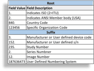
The UID functions like a serial number that is used as a name or ID, although you cannot parse the UID to understand the content it represents. UIDs exist to give unique identities to something, not to carry information about the thing they identify. The UID uses the structure defined by International Organization for Standardization/International Electrotechnical Commission (ISO/IEC) 8824-11 for OSI object identifiers. It has two parts: the root and the suffix. The root identifies the organization (see the example in Figure 1), and is appended with additional numeric fields to create the suffix. The organizational root is registered with DICOM (per PS3.5 Annex C) and the National Electrical Manufacturers Association (NEMA), and will differ for each manufacturer or user. The format and use of the suffix is up to an individual organization to control. The organization can specify how it labels fields for the information it needs. See Figure 1 for an example of how this sample organization decided to format the suffix.
For example, a UID might look like this: 1.2.840.12345.3.152.235.2.12.187636473, where 1.2.840.12345 is the root and 3.152.235.2.12.187636473 is the suffix. There is a maximum of 64 characters; using as many of the available 64 characters as possible helps to better guarantee global uniqueness. Again, the suffix can be formatted by the organizational end user, but the root must be a registered unique number. (To obtain a registered DICOM/NEMA UID root, go to dicom.nema.org and click on “To Obtain a Unique Identifier” in the box labeled “Technical Assistance.”)
Because the UID is unique, it also makes a good name for a DICOM file. If you see a file name like 1.2.840.12345.3.152.235.2.12.187636473, you can be pretty certain that it’s a DICOM file. If you are looking at a captured text file, search for the root that’s bound to appear in a DICOM text file (ie, 1.2.840.10008). This root is used for all DICOM transaction UIDs and is set aside in the standard for this purpose.
Wrap
SCU, SCP, SOP, IOD, DIMSE, and UID—did we hit your limit on new acronyms? When you see these acronyms, you’ll know they deal with DICOM and have some idea as to what they represent in the protocol. If you’ve persevered through this Reader’s Digest version of the DICOM standard and have actually visited the website, congratulations! You’re well on your way to DICOM geekdom.
In part 2, we’ll complete the puzzle by looking into the aspects of network communication, especially how AEs agree on format in the association process. At that point, we’ll have enough background to delve into the conformance statement to see how OEMs stipulate to what extent they’re DICOM-compatible.
Jeff Kabachinski is the director of technical development for Aramark Healthcare Technologies in Charlotte, NC. For more information, contact chief editor Jenny Lower at [email protected].


