Ethernet is easily the most widespread communication method for local area networks (LANs). Being low on the OSI model hierarchy, Ethernet needs to perform its duties before any other network communication can happen. Since Ethernet is so prevalent, and so fundamental to the OSI model, it becomes essential for HTM professionals to know the basic operational and technical framework.
This is the first of a two-part series covering Ethernet and its protocols and processes. To build a solid understanding, we’ll need to explore the media access protocol called Carrier Sense Multiple Access with Collision Detection (abbreviated CSMA/CD) and data packet architecture. That is the subject of this first part. Ethernet data packet architecture and a slot time discussion will come next month in part 2.
Accessing the Media
Network arbitration—or how to get data on and off the line—happens within each of the network nodes. Network access is managed by the Ethernet circuitry and protocol. Ethernet is governed by the IEEE standard 802.3, Carrier Sense Multiple Access with Collision Detection, which essentially spells out what happens in the Ethernet functional flow.
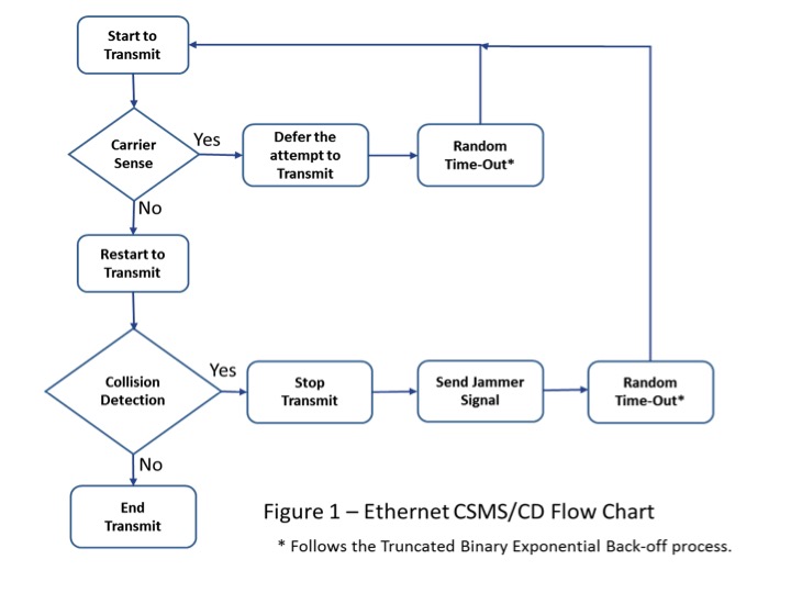
Figure 1: Ethernet CSMS/CD Flowchart. (Click to enlarge.)
Consider the Ethernet process flow as shown in Figure 1. Ethernet is asynchronous serial communication in that there is no extra line for a clock signal. The clock timing is built into the transmission, modulated in with the data.
The transmission process begins when the node is ready to send a data packet, a train of 1’s and 0’s assembled into a packet or message frame. During the carrier sense phase, represented by the second block in Figure 1, the transmitting node checks the cable to see if another signal is already present. Think of it as a voltage detector that senses a carrier’s voltage, checking to see if there is another transmission or someone else talking on the cable at that moment. If it senses a carrier voltage, it means the network cable is in use, and the node will have to wait its turn.
Random Time-Out
The node must hold back the attempt to transmit when a carrier is sensed and wait for a quasi-random amount of time, determined by a short algorithm. The wait time is based on the Truncated Binary Exponential Back-Off calculation. It’s a short algorithm that returns a random number based upon how many times the node attempts to transmit. (It is also one of my favorite terms. I like the way it rolls off the tongue, and if used strategically, it could make you sound good in network discussions!)
Consider the formula: a random number r is based on 2K where K is the number of attempts to transmit. The random number is between 0 and 2K, and is stated as 0 < r < 2K. Consequently, the first time we attempt to transmit, K equals 1. 2 to the first power equals 2. A random number between 0 and 2 is 1. This means we wait one increment of the back-off time factor.
In this case, the time factor increment for the standard 10 MBits/s data rate is 51.2 ?S. We’ll see where that number comes from and how it can change in part 2 of this column. This is a critical value to wait, because it is how long the shortest Ethernet packet can be occupying the line. Crunching the numbers, the constant used is 51.2 ?S. The node waits, essentially twiddling its thumbs, until the wait time expires. After the time expires, it goes back to the top of the flowchart to start the transmission attempt of the same packet once again.
The next step is to go back to check the carrier sense voltage detector to see if there is a carrier present on the wire, indicating that some other node is currently transmitting. If there is, we’ll have to wait again. But now, since this is the second time, the equation makes K=2. And since 2 squared is 4, the random number becomes 1, 2, or 3—that is, a number between 0 and 4.
Let’s say the random number this time is 3. That means the node will have to wait 153.4 ?S (3 x 51.2 ?S).
The wait variable (the K variable) has a built-in maximum of 10, and will continue to stay at 10 until it finally gets a chance to transmit. Therefore, the maximum random number is 1,023 and the entire range of back-off values becomes 1 to 1,023 (0 < r < 1,024). Once this maximum number is reached, you might get a message on your screen or in a network activity log that says, “Ethernet busy,” “LAN has high traffic,” or something about having trouble getting to transmit.
This process is somewhat like driving your car. When you come down your driveway, you look both ways for traffic before merging. When your Ethernet carrier sense voltage detector indicates that it’s not sensing a carrier, seeing a clear traffic lane, then it can start to transmit its serial train.
Collisions
But wait: while the node is transmitting, it starts looking to another ‘”voltage detector,” which will tell the node if it has been involved in a collision.
If the node runs into another data packet, the voltages on the wire will change. The collision detection voltage detector is keeping an eye on what’s happening while the node is transmitting. If a collision is sensed, it stops sending and will have to wait, using the same back-off process. In addition, according to protocol, the node sends out a jammer signal, as shown in Figure 1.
A jammer signal is nothing more than 4 bytes of all 1’s, which equals 3.2 ?S of a carrier signal at the common signal rate of 10 MBits/s. Every other node on that LAN also has “carrier sense voltage detectors” that will see the jammer as a carrier, ultimately forcing all communicating nodes to go back to the top of the flow chart to start over. You could say that it resets the network.
If there are no collisions, the node continues to send out its data packet until it has been completely transmitted. The node at this point readies the next packet for transmission.
The arbitration of getting into traffic is driven by each node via this Ethernet routine. One way to put this is that it is multiplexing network traffic on a multi-access media. Every LAN node has an equal chance to communicate.
Wrap Up
Ethernet continues to thrive as the most popular LAN access technique. The protocol and methods have stood the test of time. The Ethernet spec has had some 50 or so revisions since the early 1980s, when it first rolled out.1 It’s interesting to see what kinds of things are around the corner for Ethernet. A look at the brief listing of the standard’s upcoming revisions shows that speeds up to 400 GBits/s over a multi-fiber optic cable and 40 GBits/s for balanced twisted pair are on the drawing board. Also planned is the ability for Ethernet to provide up to 100 W of power over the cabling infrastructure.1 Wow—these things are beginning to happen now. All we need is for our Internet access providers to upscale their equipment too!
In part 1 of this article, we have looked at how packets are sent: the arbitration for access to the LAN’s media. The key takeaway from this is that it is the nodes that do the work of getting their data packets onto the media. In the next installment of this short series, we will examine the Ethernet data packet architecture, review how data packets are addressed and received, and talk more about back-off time, also known as slot time.
Jeff Kabachinski is the director of technical development for Aramark Healthcare Technologies in Charlotte, NC. For more information, contact editorial director John Bethune at [email protected].
References
1. Wikipedia. IEEE 802.3. Available at: http://en.wikipedia.org/wiki/IEEE_802.3. Accessed April 27, 2015.