 |
Isolated power systems were originally developed to reduce the risk of fire and explosion during surgical procedures using flammable anesthetics. Because the power conductors in these systems were electrically isolated from ground, the likelihood of electrical arcing to ground (representing a potential ignition source) was reduced. Conductive flooring, explosion-proof receptacles and plugs, enhanced grounding, and isolated power were installed in operating rooms to make the use of flammable anesthetics less hazardous. However, flammable anesthetics are no longer used in health care facilities in the United States.
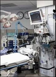
In the 1970s, extensive efforts were made to mitigate the perceived microshock hazard. This was in response to research findings that microampere-level currents applied directly to the heart could induce fibrillation. Health care facilities worked to reduce leakage currents to the lowest levels possible anywhere a direct cardiac connection might occur. For a time, isolated power systems were regarded as beneficial in this effort. As a result, isolated power continued to be installed in operating rooms and, increasingly, in intensive care units. However, isolated power systems have little effect on leakage currents.1 Therefore, national standards have moved away from specifying isolated power as a method for reducing the microshock hazard.
Isolated power remains in the National Electrical Code (NEC) as one means for reducing the hazard of electrical shock in “wet locations.” It is important to note that the term “wet location” has a very specific meaning in the NEC when applied to health care facilities. Questions have been raised as to whether or not modern operating rooms fall within this specific definition.
Regardless of the uncertain definition, it is not clear that significant hazards exist in modern clinical practice that can be mitigated by isolated power systems. The potential benefits must be balanced against the costs of installation and maintenance and the possibility that isolated power systems may have adverse effects as well.
Background Information
 |
The primary source for guidance on isolated power systems in health care facilities is the National Electrical Code (NFPA 70).2 This standard has been adopted by, and has the force of law, in all states. Information based on NFPA 70 is also found in the Standard for Health Care Facilities (NFPA 99).3 The latest edition of the Health Care Facilities Handbook, which contains the text of NFPA 99 plus additional explanatory material, is well worth having in every clinical engineering department library.
The fundamental characteristic of an isolated power system is that electrical power supplied by the system is “isolated” from ground (ie, not referenced to ground). In an isolated power system, two conductors (referred to as line 1 and line 2) supply power to equipment and receptacles. These conductors are analogous to the “hot” and “neutral” conductors that supply power in a conventional (ground-referenced) power system. Both systems also include a third conductor providing a connection to ground.
In a conventional power system that is properly installed and maintained, the voltage from neutral to ground is near zero, whereas the voltage from hot to ground is approximately 120 V AC. Connecting a low impedance pathway from hot to ground will allow heavy current to flow. If this current passes through a person, serious electrical shock can occur.
In an ideal isolated power system—one with perfect isolation—the voltage from either line 1 or line 2 is undefined. Connecting a low impedance pathway from either line to ground would not produce any current flow.
In a real isolated power system (one that can actually be manufactured), the voltage from either line 1 or line 2 typically measures around 60 V AC on a high impedance voltmeter. This is because real systems typically have roughly balanced faults on each line. Connecting a low impedance pathway from either line to ground will produce some current flow, typically in the range of a few milliamperes. Better isolation allows less current; degraded isolation allows more current.
Below are some basic definitions from NFPA 99 (numbers in square brackets indicate the paragraph of NFPA 99, 2005 edition, from which the material is taken):
- Isolated Power System (IPS). A system comprising an isolating transformer or its equivalent, a line isolation monitor, and its ungrounded circuit conductors [3.3.85].
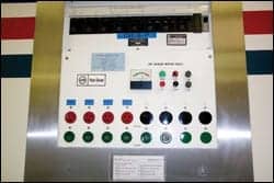
- Line Isolation Monitor (LIM). A test instrument designed to continually check the balanced and unbalanced impedance from each line of an isolated circuit to ground and equipped with a built-in test circuit to exercise the alarm without adding to the leakage current hazard [3.3.99]. The line isolation monitor shall be designed such that … a red signal lamp and audible warning signal shall be energized when the total hazard current reaches a threshold value of 5.0 mA under normal line voltage conditions [4.3.2.6.3.2]. An ammeter connected to indicate the total hazard current of the system shall be mounted in a plainly visible place on the line isolation monitor with the “alarm on” zone at approximately the center of the scale [4.3.2.6.3.4].
- Hazard Current. For a given set of connections in an isolated power system, the total current that would flow through a low impedance if it were connected between either isolated conductor and ground [3.3.66].
It is important to note that the hazard current, the reading displayed on the LIM, is a predictive value. For example, a reading of 2.0 mA does not mean that two milliamperes of current are flowing from either line to ground; it means that the system isolation has degraded to the point that two milliamperes could flow from line to ground through a low impedance pathway. For this reason, a LIM alarm does not indicate that an immediate hazard exists; it indicates that a potential hazard has developed.
Patient Care Areas
 |
| The potential benefits of isolated power systems must be balanced against the costs of installation and maintenance and the possibility that they may have adverse effects as well. |
NFPA 99 requires the hospital’s “governing body” to designate patient care areas within the facility [13.2.4]. For this purpose, a patient care area is defined as “any portion of a health care facility wherein patients are intended to be examined or treated” [3.3.138]. In addition, each patient care area is to be classified as either a general care area or a critical care area.
General care areas are “patient bedrooms, examining rooms, treatment rooms, clinics, and similar areas in which it is intended that the patient shall come into contact with ordinary appliances such as a nurse call system, electric beds, examining lamps, telephones, and entertainment devices” [3.3.138.2].
Critical care areas are “those special care units, intensive care units, coronary care units, angiography laboratories, cardiac catheterization laboratories, delivery rooms, operating rooms, postanesthesia recovery rooms, emergency departments, and similar areas in which patients are intended to be subjected to invasive procedures and connected to line-operated patient-care-related electrical appliances” [3.3.138.1].
A patient care area (general or critical) may also be classified as a wet location, which is defined as “an area in a patient care area where a procedure is performed that is normally subject to wet conditions while patients are present including standing fluids on the floor or drenching of the work area, either of which is intimate to the patient or staff” [3.3.185]. Annex A (not an official part of the standard) notes that “routine housekeeping procedures and incidental spillage of liquids do not define a wet location” [A.3.3.185].
Finally, a patient care area may also be classified as an anesthetizing location [13.2.5], which is defined as “any area of a facility that has been designated to be used for the administration of nonflammable inhalation anesthetic agents in the course of examination or treatment, including the use of such agents for relative analgesia” [NFPA 99 (2007) 3.3.9]. Note that NFPA 99 no longer addresses flammable anesthetizing locations, except in an annex to the standard.
Some typical classifications that might be adopted by the governing body in consultation with clinical staff and clinical engineering personnel:
- Nursing station: nonpatient care area.
- Patient room on a medical-surgical unit: general care area.
- Hydrotherapy treatment area: general care area, wet location.
- Patient room on an intensive care unit: critical care area.
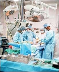
- Operating room: critical care area, anesthetizing location.
Where Is Isolated Power Required?
 |
| Isolated power systems were regarded as beneficial in reducing leakage currents and were installed in operating rooms. |
If an area of the health care facility is classified as a wet location, then ground fault circuit interrupter (GFCI) circuits or an IPS must be installed [4.3.2.2.8.1]. The GFCI option is allowed only when the interruption of power can be tolerated [4.3.2.2.8.5]. Thus, the GFCI option may be appropriate in a hydrotherapy treatment area. But, because interruption of power cannot be tolerated in an operating room, classification of operating rooms as wet locations means that isolated power is the only option.
Therefore, the decision of whether or not to classify an area of the health care facility as a wet location is critical in terms of the type of electrical system that must be installed. The most controversial issue has been whether or not operating rooms are wet locations, as defined by NFPA 99. A growing consensus holds that they are not.
Department of Defense guidelines for medical facilities state that “operating rooms, delivery rooms, cystoscope rooms, oral surgery, cardiac catheterization rooms, and other such rooms are not wet areas.”4 In the past, the Veterans Administration mandated classification of operating rooms and cardiac catheterization laboratories as wet locations requiring isolated power;5 however, that directive has expired and a task force has recommended removal of the mandate.
ECRI Institute’s most recent position is that “the use of isolated power systems in the OR is unnecessary and of no significant benefit to patient safety.”6 An extensive survey of health care facilities conducted recently for Mazzetti & Associates found that “the general trend appeared to be away from the use of IPSs in ORs.”7
Evidence-based Engineering
What is the evidence regarding the hazards targeted by IPS? In recent years, many operating rooms have been constructed without isolated power. However, no evidence has appeared suggesting that these operating rooms have caused harm to patients or staff.
Vernon and Nash collected data from Kaiser Permanente facilities regarding problems that might be related to electrical systems in operating rooms, about half of which had IPSs. They found that such problems were rare but concluded, “The Kaiser evidence-based results show that not only do IPSs not provide the promised benefits, but also that the side effects may themselves be harmful.”7
How to Decide
The first step is to decide if a specific patient care area such as an operating room is a wet location under the NFPA 99 definition. Include clinical representatives and clinical engineering personnel in the decision. Also, determine if any authority having jurisdiction relevant to your facility has requirements in this regard. For example, the state of North Carolina requires isolated power in operating rooms and intensive care units. This decision should be submitted for confirmation by the governing body and documented for future reference.
If you decide that the area is a wet location, install GFCI circuits (if interruption of power is tolerable) or an IPS (if interruption of power is not tolerable). If an IPS is required, budget for the fact that “in addition to the initial acquisition cost, isolated power systems present an ongoing testing and maintenance burden.”6
If you decide that the area is not a wet location, you may install a conventional—or ground referenced—power system.
The more you know about applicable codes and available evidence, the better you will be able to participate in effective decision-making about IPSs. You will likely encounter a wide range of strongly held opinions, not all of which are based on accurate information. Know your codes and regulations, and help your facility make good decisions.
Matthew F. Baretich, PE, PhD, is president of Baretich Engineering, Fort Collins, Colo, (www.baretich.com) and is a member of 24×7’s editorial advisory board. He provides clinical engineering, health care facilities engineering, and safety management consulting, and incident investigation and forensic engineering services. For more information, contact .
References
- Shepherd M, Baretich MF. Electrical Safety Manual. 2004 ed. Arlington, Va: Association for the Advancement of Medical Instrumentation; 2004.
- Early MW, Sargent JS, Sheehan JV, Caloggero JM, eds. National Electrical Code Handbook. NFPA 70. 9th ed. Quincy, Mass: National Fire Protection Association; 2005.
- Bielen RP, ed. Health Care Facilities Handbook. NFPA 99. 7th ed. Quincy, Mass: National Fire Protection Association; 2005.
- Department of Defense. Medical Military Facilities: Design and Construction Criteria. MIL-HDBK-1191.
- Veterans Health Administration. Electrical Safety Policy for Patient Care Equipment. Directive 2002-030.
- ECRI Institute. Electrical safety Q&A: A reference guide for the clinical engineer. Health Devices. 2005;34(2):57-75.
- Vernon W, Nash H. Isolated Power: The Final (Two) Words. San Francisco, Calif: Mazzetti & Associates; 2004.