Although the technology is highly complex, in-house and third-party servicers are doing more maintenance of MRI equipment
By Brian Bean, CRES
X-ray and CAT (CT) scan technologies are both good at imaging bones and other dense objects in the body, but when it comes to soft tissues like the brain, heart, spinal column, and ligaments, magnetic resonance imaging (MRI) is unmatched. Last year, 30 million MRI exams were performed in the United States, the culmination of a 10% rate of growth every year for the last 10 years, a trend that shows no sign of slowing down any time soon.1,2
Because of the costs and complexity entailed in MRI, equipment maintenance and service have been performed predominantly by the manufacturers. However, because of the maturity and continued expansion of the field, the opportunities for in-house service and third-party companies have been growing. This article is intended to be an overview of MRI basics for those service professionals who may soon find themselves maintaining MRI equipment.
Physics

FDA-approved labels from the ACR guidelines. They should be used for all equipment in an MR environment. Green = MR safe, yellow = MR conditional, red = MR unsafe
MRI creates an image using the phenomenon known as nuclear magnetic resonance (NMR), which simply means that the nucleus of an atom in an external magnetic field has properties that allow it to absorb and retransmit electromagnetic energy at a resonant frequency. The proton in the nucleus of a hydrogen atom will align itself with a magnetic field and will wobble or precess at a frequency of about 64 MHz for a 1.5 Tesla magnet, the most common strength MRI in use today.
Energy added to the proton in the form of a radio frequency (RF) pulse will be absorbed and will tip the proton out of alignment with the magnetic field. The proton will then realign itself with the field, releasing RF energy in the process. It is this RF signal, known as the free induction decay (FID) signal, that is used to produce the MRI image.3 Hydrogen atoms are used in MRI because not only are humans 80% water, but hydrogen atoms also exist within all of the other liquids, fats, tissues, and other components of the body, and on a plentiful scale (as in thousands of trillions per cubic centimeter).
In CT, an x-ray machine rotates around the patient, which limits slice acquisition to the axial plane. MRI has no such limitations, and can acquire image slices in any orientation. MRI has this capability because it uses gradient coils to vary the magnetic field strength and nuclear resonant frequencies in any axis. This allows for the selection of specific bands or slices in the sagittal, coronal, axial, or oblique planes.
A receiver coil is used to collect the FID signal, which can be a body coil that is built into the gantry or a localized coil used for a specific body part. Often the body coil is used to generate the pulse, and a smaller localized coil is used to pick up the faint FID signal. Other localized coils, such as head or knee coils, are able both to transmit and then to receive back the RF signal.
Collecting data for a single slice requires a series of RF pulses to be transmitted and then echoed back for each line of data in a slice for every slice throughout the image field of view (FOV). Once the FID data is collected, it is digitized and processed using Fourier Transform analysis to produce the final image.
In addition to creating magnetic gradients for slice selection, gradient coils are also used to encode additional information to set up an image matrix within each slice. Phase information is encoded, creating one axis of the matrix. Frequency information creates the other axis. The result is that each slice contains a matrix of 3D volume elements, or voxels, that are used to create the MRI image.4
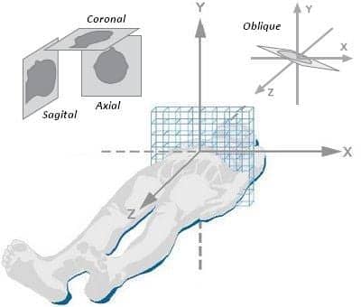
An 8×8 matrix of an axial slice of data. Although slices can be acquired in any orientation, as seen here, also shown is the conventional labeling system for the x, y, and z planes.
A typical MRI study consists of several series of 2D images, but 3D image reconstructions are also possible, and are commonly used for imaging arteries and veins. There are dozens of different protocols that use a variety of techniques by which information is encoded and read back—too many, in fact, to be discussed here. However, they all rely on well-timed orchestration between the RF pulses being sent and echoed back while the gradient coils are switching on and off. Generating images this way is time-consuming: a brain exam can take 15 minutes, while a spine or cardiac exam can take 90 minutes or more. The process is also very noisy. Gradient coils are high power and make hammering noises as they are switched on and off, requiring ear plugs or headphones inside the exam room.
A typical MRI exam consists of a set of five to 10 acquisition sequences. Technologists are also responsible for adding or changing sequences to get the optimum image. There is never any one right answer for the best sequence or technique to use, because no two MRI exams are exactly the same.
Even after the desired sequence has been chosen, there are still more than a dozen parameters that must be customized by the technologist, such as FOV, slice thickness, and matrix size. And here again there is never any one right approach, because there are always trade-offs. For example, a smaller voxel size may help distinguish smaller objects, but it will produce a weaker signal because of fewer protons. Smaller voxels also require more pulses to cover the same area, resulting in longer acquisition time. Other adjustments are made by technologists “on-the-fly” during the exam, either to enhance an area of interest or to compensate for a patient’s anatomy or movement. All in all, the work of an MRI technologist is more of an art than a science.
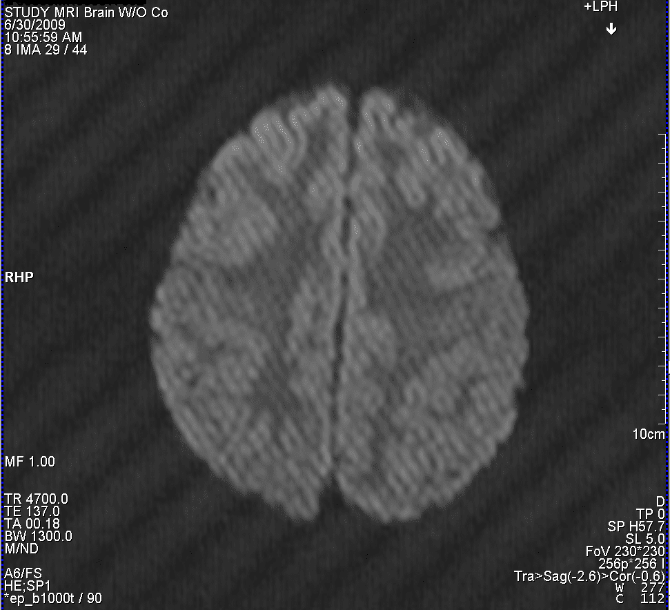
A spike artifact can be seen in this axial brain image. Note how a single noise spike during acquisition shows up as a series of stripes when processed with a Fourier Transform.
Obtaining the optimal spatial resolution, which is on the order of a couple hundredths of a millimeter, requires not only that the patient remain motionless for the entire exam but also that the magnetic field be homogenous. Typically, a sphere at the isocenter of the gantry is designated as having a uniform field to within a couple of parts per million. To compensate for anomalies in the field from internal and external sources, metal shims are inserted around the bore of the magnet. Coils are also used to actively shim the magnet. Other coils are used to limit the undesired part of the magnet field (fringe field) that extends outward from the gantry. A distance from the gantry where the field strength is down to a level of 5 gauss is generally considered a safe distance. With good shielding, the distance of the 5-gauss line can be reduced to within 5 feet of the bore.
Keeping the 5-gauss line as close to the gantry as possible helps avoid interference with other equipment in the room. However, doing so can also be deceiving, because this means that the field strength increases from 5 gauss to 1.5 Tesla in a matter of a few feet.
Gauss and Tesla are both units of measure of magnetic field strength for a given area, and 1 tesla equals 10,000 gauss. To get an idea of what a gauss is, consider this: 1 gauss is equal to 6.5 magnetic lines of flux per square inch, roughly equal to the area of the circle made by touching your fingertip to your thumb.5 Note that, as the earth’s magnetic field is roughly 0.5 gauss, there are three or four lines of flux in an area that size passing through us all the time, circling from the North to South Pole. At 5 gauss, there are around 33 lines through that same area. By the time you reach the center of the bore, the field has become so concentrated that close to 100,000 magnetic field lines fit in that same area circling from out the front (North Pole) of the gantry around to the rear (South Pole).
Instrumentation
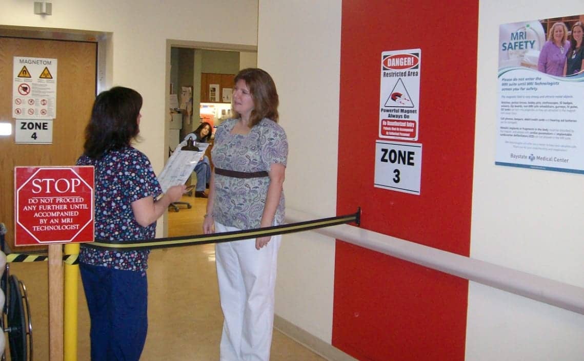
All patients need to be thoroughly screened before entering an MRI suite. Note the physical barrier to prevent anyone who has not been screened by a technologist from simply walking into the scan room.
Apply a battery to a foot of copper wire wound in a coil, and you have created a small electromagnet solenoid. Put 500 amps through a mile of coiled copper wire, and you’ve created a 1.5 Tesla electromagnetic solenoid MRI machine. Unfortunately, using copper wire is unrealistic. Because of the resistances in copper, you would need around 50,000 volts to drive the MRI, producing a whopping 25,000 kilowatts of power. To overcome this limitation of copper, niobium-titanium wires are used, submerged in liquid helium that keeps them at a few degrees above absolute zero and in a state of superconduction, where they have zero resistance.6
This is why MRI gantries are so large. They are actually large cryostats or vessels for containing liquid helium, usually on the order of 1,000 liters. A power supply is used to inject current into the system. Once ramped up, the power source is removed and the hundreds of amps of current travel continuously until it is ramped back down or there is a fault condition.
In a fault condition, the magnet quenches, meaning that the system heats up and the wires become resistive, resulting in boil-off of the liquid helium and a collapse of the magnet field. A quench can occur spontaneously because of an equipment malfunction or manually by pressing the quench button. Either way, it is a costly event, requiring machine downtime while cryogens and magnet power supply are shipped out, the cryogens are refilled, and the magnet is ramped back up. In addition, since each liter of liquid helium converts to 750 liters of gaseous helium, it is crucial that the quench pipe be in good working order to vent these gases so that they don’t fill into the MRI room, displace oxygen, and result in asphyxiation.
Safety
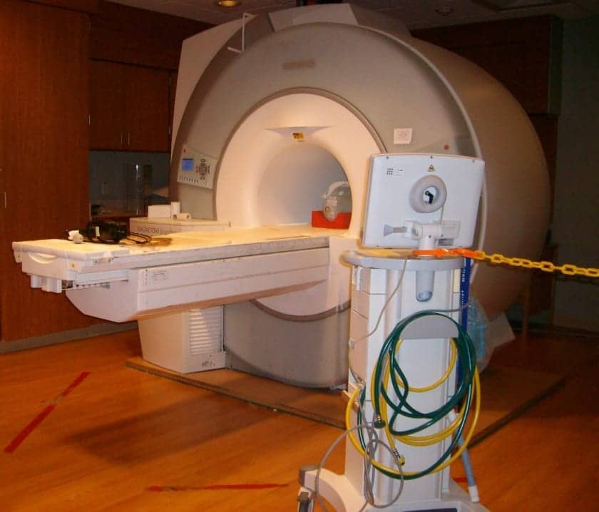
The red tape on the floor identifies the 5-gauss line in front of this Siemens Espree MRI. The tether on the MRI conditional ventilator is to prevent it from reaching the 5-gauss line, as per the manufacturer.
There is always the risk of a ferrous metal object being brought into the vicinity of the magnetic field, where the potential for damage, injury, and death is a real possibility. Restricting access and clearly labeling the magnet and MRI suite go a long way toward making people aware of the dangers.
The American College of Radiology (ACR) is largely used as the authority on MRI safety, and its Guidance Document on MRI Safe Practices has been updated for 2013.7 Some of the document’s highlights are that an MRI suite should be divided into four clearly marked zones. Zone 1 is accessible to the general public; zone 2 is the screening area, where all ferrous materials are removed and stored; zone 3 is for patients and family members that have been screened (it should contain a physical barrier such as a gate for restricting access); and zone 4 is the scan room itself. This document also shows the labeling standard set by the FDA for mobile items in an MRI suite.
Service
From a service perspective, the high power gradient and RF power amplifiers are often water-cooled, meaning that the water temperature, flow rate, and pressure should be routinely monitored. Caution should also be used anytime work is done inside the gantry or equipment cabinets, since there are high-voltage wires and water hoses side by side. Helium compressors are also used as part of the “cold head” of the system, which helps reduce helium boil-off and which also creates the distinctive “chirping” noise heard inside the scan room. (Note: if a scan room is quiet, you may want to check for a fault condition. The cold head should always be running. If not, the rate of helium boil-off will increase.)
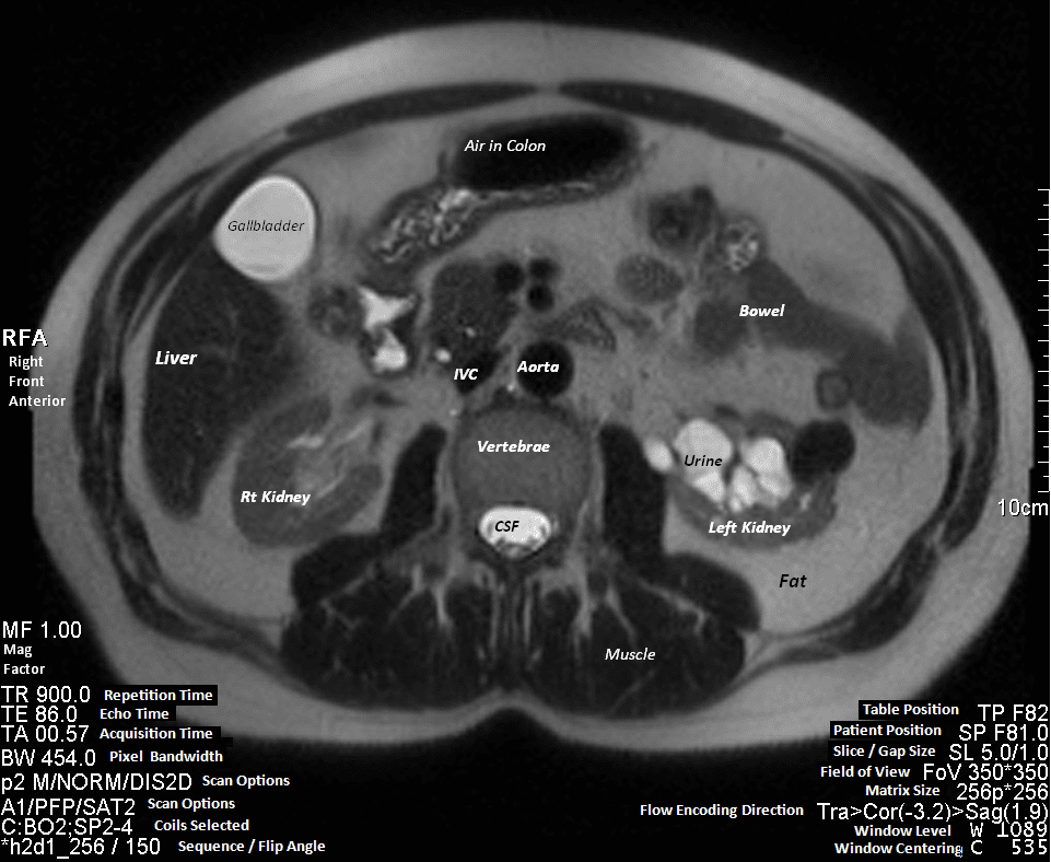
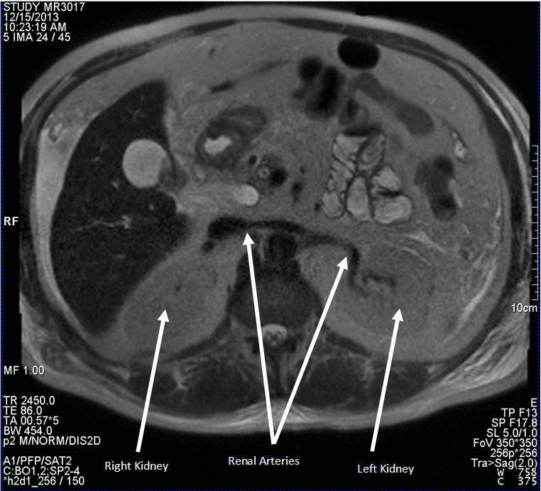
In this axial abdomen slice, notice the many shades of gray between the white cerebral spinal fluid and the black air in the colon. Note also the many parameters that must be set by the technologist. PS: can you identify the pathology? Hint; compare the right and left kidney. Find the diagnosis and more MRI images at the bottom of this page.
To reduce RF interference, MRI rooms are lined with metal, creating a faraday cage to keep out all extraneous RF signals. Copper fingers are often used to seal around the door frame. In order to seal properly, they must be kept clean and replaced as they wear out. It is also possible to develop leaks in the shielding because vibrations on the door frame and wall can cause the metal seams to open up over time, creating an RF leak.
One inexpensive way to check for leaks is to take a portable FM radio into the room and shut the door behind you. If you can still hear music, you have a substantial leak that must be addressed. Keeping RF signals out is important, because many image artifacts can be traced back to RF interference.
Spike artifacts are another common artifact. They can be caused by electrical disturbances in the room from sources such as a burned-out light bulb or from mechanical vibrations such as a loose gantry cover.
Conclusion
An OEM manufacturer is limited to servicing its own equipment. By contrast, an in-house or third-party service provider can service all of the needs of an MRI department. This includes such activities as ensuring that safety codes are being followed, providing coverage for MRI support systems such as RF shielding, quench pipes, water cooling systems, and oxygen monitoring systems. In addition, in-house or third-party services can maintain MRI-related equipment from a wide range of manufacturers.
I hope this article has succeeded in giving a helpful big-picture overview of MRI and a framework for further study. Perhaps, with enough study, you will even go as far as to join the elite few that know all there is to know about the technology. In the meantime, the vast majority of us will continue to struggle with all of the diverse complexities that make up MRI. 24×7
Brian Bean, CRES, clinical engineering, Baystate Medical Center, Springfield, Mass, has more than 20 years of experience in the biomedical field and has primary responsibility for the MRIs at Baystate Health System. For more information, contact editorial director John Bethune at [email protected].
References
1. Rinck P. Magnetic Resonance in Medicine. The Basic Textbook of the European Magnetic Resonance Forum. 7th ed. 2013. Electronic version 7.1; 1 October 2013. Available at: http://www.magnetic-resonance.org/MagRes%20Chapters/21_03.htm. Accessed January 9, 2014.
2. Today’s MRI Market. Magnetica. Available at: http://www.magnetica.com/page/innovation/todays-MRIi-market/. Accessed January 9, 2014.
3. Magnetic Resonance Imaging. HyperPhysics. Available at: http://hyperphysics.phy-astr.gsu.edu/hbase/nuclear/mri.html. Accessed January 9, 2014.
4. Jones J, Yeung J, et al. Spatial resolution MRI. Radiopaedia.org. Available at: http://radiopaedia.org/articles/spatial-resolution-mri-1. Accessed January 9, 2014.
5. Hoadley R. Magnet man. How strong are magnets? Available at: http://my.execpc.com/~rhoadley/magflux.htm, Accessed January 9, 2014.
6. Hornak J. The basics of MRI. Available at: http://www.cis.rit.edu/htbooks/mri/chap-9/chap-9.htm. Accessed January 9, 2014.
7. Kanal E, et al. ACR Guidance Document on MR Safe Practices: 2013. J Magn Reson Imaging. 2013;37:501-530. Wiley Periodicals Inc.
8. Siemens Medical. Magnets, spins, and resonances: an introduction to the basics of magnetic resonance. Available at: http://www.scmr.org/assets/files/members/documents/magnets_spins_resonances.pdf. Accessed January 9, 2014.
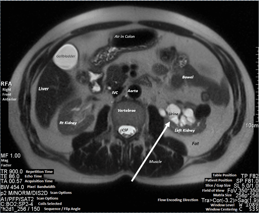
Did you spot the pathology? The backup of urine seen above in the left kidney is a condition known as hydronephrosis. Two healthy kidneys are shown below for comparison. Also pointed out are the healthy renal arteries feeding the kidneys. Notice also how the large liver displaces the smaller kidney, which is perfectly normal.