Routine electrical safety testing is frequently defended on instinct rather than evidence. An engineering analysis shows what actually protects patients and staff.
By Larry Fennigkoh, PhD, PE
In continuing the recent discussion on The Electrical Safety Testing Myth, Matt Baretich, Binseng Wang, and Steve Grimes are all spot on with encouraging the healthcare technology management (HTM) community to reevaluate why it continues to spend time doing tasks and testing that may have limited value. However, simply promoting the elimination of electrical safety testing often triggers defensive, near-blasphemous reactions, particularly among clinicians, administrators, and even some technical staff. Fortunately, when such testing is viewed from engineering and scientific perspectives, considerable clarity and new reasoning may emerge.
What is being challenged and discouraged is the routine measurement of 60 Hz device leakage (or touch) currents on in-service medical equipment that has not undergone repair, modification, or abnormal stress. What should not be eliminated are several inspection and verification activities that remain fundamental to electrical safety, grounding integrity, and electromagnetic compatibility. The foundation of which begins with an understanding of where leakage current comes from.
The Electrical Origin of 60 Hz Device Leakage Currents
Virtually all AC line-operated medical devices with an electrically conductive case—or conductive surface(s) capable of being energized from within—will exhibit a measurable 60 Hz leakage current from such a surface to earth ground. The origin of this current is not a defect, but the unavoidable consequence of operating the device from an energized AC power line.
From an AC circuit’s perspective, the conductive pathway from the “hot” side of the incoming power line to the device case can be represented by an equivalent series resistor–capacitor (RC) network. In some cases, the capacitive component is intentional, as in the specialized Y-capacitors used in RF/EMI power-line filters. More commonly, it arises from stray or parasitic capacitance, which exists whenever an insulating material separates two conductors. In this sense, the device enclosure itself effectively becomes one plate of a virtual capacitor.
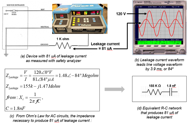
As described in Figure 1, the impedance of either this real or virtual R-C network determines the magnitude of the available and measured leakage current and can be readily determined experimentally. Here, and in Figure 1(a), a leakage current of 81 μA is conventionally measured with a safety analyzer. It can also be displayed as an 81-mV signal across a 1K ohm current sense resistor, along with the incoming 120-volt (RMS) signal powering the device (Figure 1(b). Because the leakage current leads the voltage producing it, this automatically implies that a resistive-capacitive impedance is present. The magnitude and phase of this impedance can be calculated, Figure 1(c). Its rectangular form now reveals the equivalent values of the series R-C network shown in Figure 1(d). It is such an electrical equivalent that couples the ‘hot’ side of the power line to the device’s case and establishes the magnitude of the now-available leakage current.
This leakage current is also inherently limited by design, not by aging, routine use, or normal environmental conditions. Of course, anything that reduces this effective impedance, e.g., carbon dust from the centrifuge motors, moisture, will increase the measured leakage current.
What Remains Essential: Visual Inspection and Ground Integrity
The elimination of routine leakage current measurements does not imply—nor should it ever be interpreted as—a relaxation of electrical safety vigilance. Routine visual and mechanical inspection of the device power-entry system remains vital. This includes inspecting the line cord for cuts or abrasions, verifying an intact strain relief at both the device and plug ends, and inspecting the plug cap barrel for damage, loose or bent blades, or loose screws in non-molded plugs.
Equally important is verifying ground pin-to-case continuity. Even devices with predominantly nonconductive external enclosures frequently incorporate RF/EMI power-line filters that depend on a low-impedance connection to earth ground for proper operation. A compromised ground does not merely affect measured leakage current values; it degrades fault-current diversion and reduces the effectiveness of electromagnetic interference suppression.
Necessary Conditions for Electrical Macroshock: A Five-Factor Model
As illustrated in Figure 2, for a patient or staff to experience an electrical macroshock from a medical device, five independent and necessary conditions must all be present simultaneously:
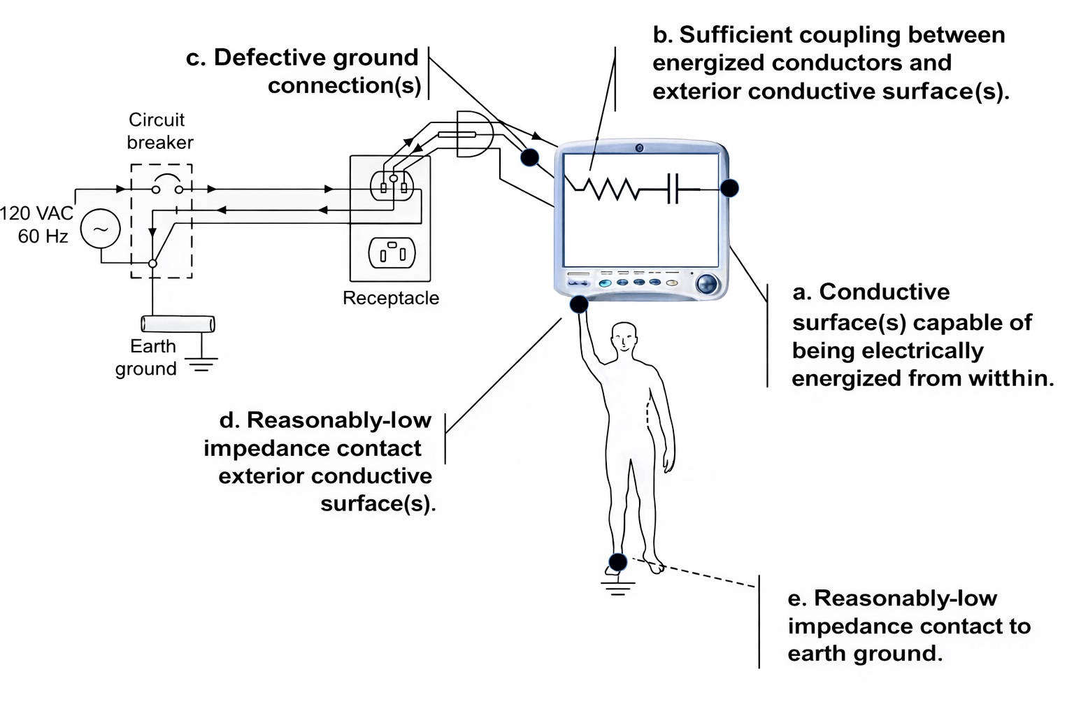
a. The device must have an electrically conductive case(s) or surface(s) capable of being energized from within.
b. The impedance of the effective R-C coupling to such a conductive surface must be low enough to produce a perceptible leakage current, i.e., one that is felt as a ‘shock.’ Experimentally, the threshold of perception for such currents is typically in the 200-300 microamp range.
c. The device must have a defective, open, or high-impedance connection to earth ground. When intact, this ground path will not only shunt any gross line-to-case fault currents, but also any present leakage currents to ground. In this regard, ensuring intact ground connections is what really protects against macroshock – not the simple knowing its leakage current values.
d. The patient or staff must have reasonably low-impedance contact with the energized surface.
e. Lastly, and to complete the electrical circuit needed, the patient or staff must simultaneously have a low-impedance connection to earth ground.
Eliminating any one of these conditions eliminates the shock hazard entirely.
Why Routine Leakage Current Measurements Add Little Risk Reduction
Routine leakage current testing evaluates only one element of this five-condition model: the magnitude of electrical coupling under nominal conditions. It does not assess grounding integrity, human contact impedance, posture, footwear, environmental grounding, or the simultaneous presence of multiple independent failure modes.
Modern medical devices are designed, tested, and certified to stringent international standards, including IEC 60601-1, which strictly limit allowable leakage currents well below physiological harmful thresholds. In regular service, absent physical damage or improper repair, these values tend to remain stable over time.
The Compound Probability Argument
Each of the five necessary conditions for shock is individually and relatively uncommon in modern healthcare environments. When treated as independent events, the probability that all five occur simultaneously becomes vanishingly small—so low as to approach the near impossible. Consequently, and from a risk-management perspective, routine leakage current testing is a very low-yield control activity, ie, quite useless.
Reframing Electrical Safety as Risk-Based Engineering
Eliminating routine leakage current measurements is not a retreat from safety, but a realignment with engineering reality. By focusing on visual inspection, grounding integrity, failure history, functional performance, and reliability, HTM programs can redirect limited resources toward risks that meaningfully affect patient care, clinician safety, and equipment availability.
References
- Fennigkoh, L. The realities and irrelevance of medical device leakage currents. Clinical Engineering Association of Illinois Annual Meeting, 2019 Aug.
- Fennigkoh, L. Biomed 101: Leakage current measurements have nothing to do with electrical safety. TechNation Magazine. 2022 April.
- International Electrotechnical Commission (IEC). IEC 60601-1: Medical electrical equipment — Part 1: General requirements for basic safety and essential performance. Edition 3.2. Geneva, Switzerland: International Electrotechnical Commission; 2020.
About the author: Larry Fennigkoh, PhD, PE, is professor emeritus of biomedical engineering in the electrical, computer, and biomedical engineering department at Milwaukee School of Engineering.

ID 125875028 © Jake Lange | Dreamstime.com


Thank you for stating the not so obvious: “Routine visual and mechanical inspection of the device power-entry system remains vital. ”
While it may be an outdated requirement “safety testing” offers a wide-ranging risk-based opportunity for surveillance of the hospital’s device inventory.
Having performed this task as I’m sure many others can attest there were many patient safety issues uncovered and adverse events prevented by active visual, mechanical and often mundane safety checks based on a rational assessment of risk.